


Contact us
You can contact us using any
of the methods below.
Unit 3 Durham Lane
Armthorpe
Doncaster
South Yorkshire DN3 3FE
England
+44 (0)1302 836010
+44 (0)1302 831555
sales@npfasteners.com


All rights reserved
© Northern Precision Ltd.
NORTHERN PRECISION LTD
Accreditations
Northern Precision Ltd operate a quality management
system in accordance with ISO 9001.
The ISO 9001 standard is recognised worldwide and
you can be assured of the benefits of working with a
certified company knowing that our management
systems are constantly assessed and improved.

Regulatory
RoHS|WEEE Compliance
REACH Compliance
Conflict minerals
statement
Environmental Policy
Opening Hours
Mon - Fri 08:00 - 17:00


Registered in England & Wales
Company number 3275391
V.A.T Registration number
GB 684 1384 17


NORTHERN PRECISION LTD


Specialist Fasteners
for Sheet Metal
+44 (0) 1302 836010
+44 (0) 1302 831555
Tel:
Fax:
sales@npfasteners.com
Quality
Service
Reliability


Installation Method & Performance
Performance

Do not remove any extra material or
chamfer the hole as this could result in
improper installation or reduced
performance.
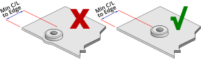
Ensure that attention is paid to the
minimum hole centreline to edge
dimension for each fastener. Installing
too close to an edge or bend could result
in improper installation or reduced
performance. Minimum centreline to
edge dimensions shown for each
fastener apply to one edge only. If this
distance is applied on multiple sides
there will be significant panel distortion
unless the panel edges are supported
during installation.
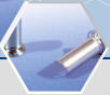
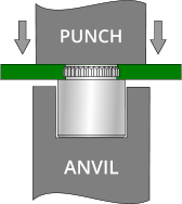
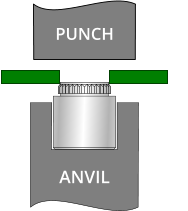
First prepare the specified hole in the panel.
Place the fastener in the anvil with the shank facing up like in
the diagram above. Locate the panel mounting hole over the
shank of the fastener.
Ensuring the panel is held level, apply a parallel squeezing force
until the shoulder of the fastener is seated against the panel.
Do not over squeeze the fastener into the panel as this will
result in panel deformation or damage.
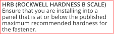
When installing broaching fasteners, please pay attention to
the minimum hole centreline to edge and parent material
hardness limitations.


A
±0.05
7.23
5.79
8.97
Thread or
Thru-hole
M3.5|3.60
M3|3.30
M4|4.20

Anvil Dimensions
Thread or Thru-hole
M4|4.20


Installation
(kN)
2.1
2.2
2.8
Pull-out
(N)
285
420
430
Torque-out
(Nm)
1.6
3.5
4.4
Test Sheet Material
1.6mm FR4 Epoxy Laminate
1.6mm FR4 Epoxy Laminate
1.6mm FR4 Epoxy Laminate


M3|3.30
M3.5|3.60
All performance figures are averages obtained over a range of installations and should be used for guidance only. Panel material, hole
preparation, installation tooling and method can affect part performance. We always recommend that you carry out your own tests in the
actual application. Please call our sales team and we will be happy to provide you with samples as well as offering technical assistance.
Material & Finish
Electro Tin Plated Steel (ET)
Stainless Steel (A2)
Maximum recommended
panel hardness: 60HRB
Part Number Examples
Part number is made up as follows:
(Type)-(Thread code or Thru-hole)-(Length)-(Material/Finish code)
For example:
CBSO-M3-8-ET (Broaching Standoff-M3-8mm long-electro tin plated steel)
CBSO-3.6-10-A2 (Broaching Standoff-3.6mm thru-hole-10mm long-stainless
steel)

Downloadable Data Sheet
Back
Dimensional
Thread
size
M3 x 0.5
M3.5 x 0.6
M4 x 0.7
Min. panel
thickness
1.53
1.53
1.53
C
±0.08
4.68
5.87
6.86
Min. CL to
edge of panel
4.40
5.50
7.10
Hole size
+0.08 -0.0
4.22
5.41
6.40
S
Max.
1.53
1.53
1.53
D
±0.13
5.56
7.14
8.74


Thru-hole
+0.10 -0.08
3.30
3.60
4.20
Info
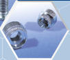
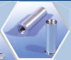
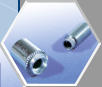
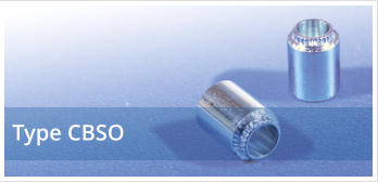
Broaching standoffs provide strong reusable threads or thru-holes in a spacer format in non-ductile materials such
as printed circuit board, polycarbonate, acrylic, glass epoxy and resin laminate components as well as ductile panels
with a maximum hardness of 60HRB.
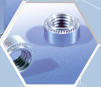
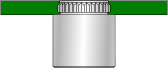
Featuring an axially knurled shank, the serrations are designed to cut into the panel material as it is installed,
resulting in an interference fit that offers good torque-to-turn resistance and pull-out performance. Installation is
simple, prepare the specified hole and using a flat punch and appropriate anvil, apply a parallel squeezing force to
press the part into the hole. When installing in printed circuit board, broaching standoffs are suitable for use in non-
plated holes only.
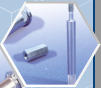
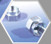
Available in metric thread and thru-hole sizes in electro tin plated steel and A2 stainless steel, broaching standoffs
are suitable for installation in panels with a maximum hardness of 60HRB.
BROACHING
STANDOFFS
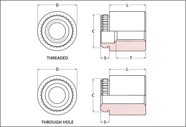

Length (L) ±0.13


Minimum thread length (T)
(where applicable)


3
4
5
6
8
10
12
14
16
Fully threaded
9.50 ±0.40


Self-Clinching Fasteners
Broaching Fasteners
Arnold & Shinjo Fasteners
Rivet Bushes
Rivet Nuts
Weld Fasteners
Cage Nuts
Blind Rivets
Inserts for Plastics
Inserts for Stone, Solid
Materials, Composites &
Sandwich Panels
Crown-Nuts
Fast-Con
Installation Equipment
Turned & Cold Formed
special parts made to order
Bespoke fastener design &
development
Fastener & Application
testing
Technical support
ISO 9001
RoHS|WEEE Compliance
REACH Compliance
Conflict minerals
Environmental Policy


SERVICES & SUPPORT

